SG-6010C Integrated Planetary Robot Joint Actuator
Product Overview
SG-6010C is a compact 80 mm planetary robot joint actuator designed for applications that require a thin axial profile, moderate torque and relatively high output speed.
It can be supplied with or without an integrated driver. Driver, encoder, communication and closed-loop control features apply only to the driver-equipped configuration confirmed in the quotation.
Engineering Evaluation Fast Track
If you are evaluating SG-6010C for a robot joint, you can immediately review the released datasheet, mechanical interface and simplified STEP model.
If the required torque, speed, ratio, diameter, thickness, motor, encoder, driver or mounting does not match SG-6010C exactly, use it as a reference platform and start a custom joint review instead of forcing the application to fit the catalog model.
View SG-6010C Engineering Resources Custom Robot Joint Development Request Engineering Review
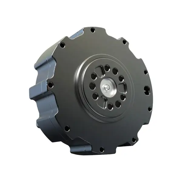
Product Identity
| Item | Description |
|---|---|
| Model | SG-6010C |
| Product type | Integrated planetary robot joint actuator |
| Transmission | Planetary gearbox |
| Configuration | With or without integrated driver |
Key Benefits
- Compact 80 mm outer diameter
- Thin 34.07 mm product thickness
- 310 rpm rated output speed
- 6 Nm rated torque and 18 Nm peak torque
- Optional integrated driver and absolute encoder
- Suitable for compact robot joints and exoskeleton mechanisms
Key Specifications
| Parameter | Value |
|---|---|
| Transmission structure | Planetary structure |
| Outer diameter | 80.0 mm |
| Product thickness | 34.07 mm |
| Reduction ratio | 9.67:1 |
| Backlash | 15–20 arcmin |
| Motor power | 328 W |
| Operating voltage | 24–48 VDC |
| Rated output speed | 310 rpm |
| No-load output speed | 400 rpm |
| Rated output torque | 6 Nm |
| Peak output torque | 18 Nm |
| Weight | 377 ± 10 g |
| Allowable radial force | 250 N |
| Allowable axial force | 100 N |
Mechanical Dimensions
- Outer diameter: 80.0 mm
- Overall thickness: 34.07 mm
Public mounting and interface information is available in the SG-6010C Mechanical Interface v1.0. Request the controlled configuration drawing before final production release.
Transmission Parameters
| Parameter | Value |
|---|---|
| Gear structure | Planetary |
| Reduction ratio | 9.67:1 |
| Backlash | 15–20 arcmin |
Motor and Electrical Parameters
| Parameter | Value |
|---|---|
| Motor power | 328 W |
| Operating voltage | 24–48 VDC |
| Phase damping | 224 µΩ |
| Phase inductance | 235 µH |
| Phase current full scale | 33 A |
| Rated bus current | 12 A |
| Static working bus current | 0.08 A |
| Motor torque constant | 0.0606 Nm/A |
| Motor structure | 18 slots / 20 poles |
| Thermistor | 10 kΩ B3435 ±1% |
| NTC B value | 3435 |
| Back EMF constant | 0.0727 Vs/rad |
| Motor KV value | 104 rpm/V |
Encoder and Sensor
The driver-equipped configuration can use the MA600 16-bit single-turn absolute magnetic encoder.
The encoder and sensor configuration must be confirmed in the quotation for versions supplied without the standard integrated driver.
Driver and Control
The optional integrated driver supports field-oriented control and closed-loop motion control.
Available control functions for the driver-equipped configuration include:
- Position control
- Velocity control
- Torque control
- MIT-style motion control
- PID parameter adjustment
- Calibration and user-zero configuration
Communication Interfaces
Publicly documented interfaces for the driver-equipped configuration include:
- CAN
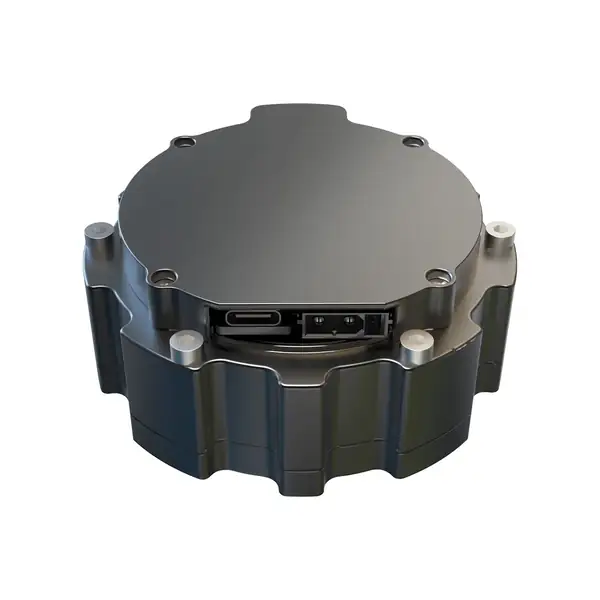
- USB Type-C for configuration and debugging
- Second encoder interface supporting I2C / UART on applicable driver-equipped configurations
Project- or driver-dependent expansion may include:
- RS485 through expansion hardware
- EtherCAT subject to project confirmation
- Additional expansion interfaces subject to engineering review
Driver hardware and firmware can evolve by ordered configuration. Confirm the driver and firmware configuration for the quoted unit before integration.
Load Capacity
| Parameter | Value |
|---|---|
| Allowable radial force | 250 N |
| Allowable axial force | 100 N |
The suitability of the actuator for external radial and axial loads depends on the installation geometry and duty cycle.
Standard Configuration
The standard mechanical assembly includes:
- BLDC motor
- Planetary reduction mechanism
- Housing and output structure
Electrical and control components depend on the selected configuration.
Optional Configuration
- Integrated driver
- Absolute encoder
- CAN control
- RS485 expansion
- Custom cables and connectors
- Custom mechanical interfaces
- Customer branding and labeling
What Is Not Included
Unless specifically stated in the quotation, the following are not automatically included:
- External power supply
- Host controller
- Communication adapter
- External brake resistor
- Application-specific mounting hardware
- Detailed production drawing or internal assembly documentation
Recommended Applications
- Humanoid robot joints
- Exoskeleton joints
- Quadruped robot joints
- Compact robotic arms
- Rehabilitation robots
- Research and education platforms
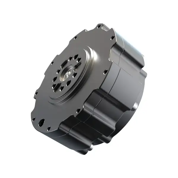
Product Images
| Output and mounting views | Driver and interface views |
|---|---|
 |
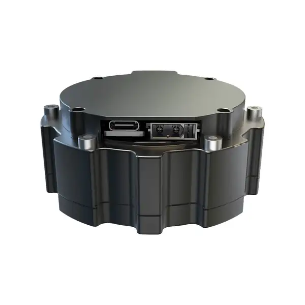 |
| Output mounting face | Side interface and connector view |
 |
|
| Rear interface view | Front-angle product view |
The images show one product configuration. Connector, driver, encoder and mechanical-interface details must be confirmed for the quoted version.
Engineering Resources
The following SG-6010C v1.0 public engineering resources are approved for engineering evaluation and early mechanical design-in:
Download Datasheet v1.0 Download Simplified STEP Model v1.0 Download Mechanical Interface v1.0
The public STEP model is a simplified external-interface model intended for layout, envelope and mounting evaluation. It does not expose the internal gear train, motor internals, bearings, PCB or other internal construction details.
Integration Documentation
Detailed CAN protocol documentation, Quick Start instructions, firmware-specific integration notes and related support files are provided after inquiry so the documentation can be matched to the selected driver and firmware configuration.
Request Integration Documentation
Custom Development, Evaluation and Design-In
Custom Robot Joint & Compact Actuator Development Sample Validation Workflow Design-In Checklist
For final design release, confirm the ordered configuration, controlled mechanical interface, driver configuration and application operating conditions with SigGear.
Selection Information Required
Please provide:
- Application and installation position
- Rated and peak torque
- Required output speed
- Operating voltage
- Size and weight limits
- Duty cycle
- Driver and encoder requirement
- Communication interface
- Estimated prototype and annual quantity
Related Selection and Application Guides
Robot Joint Actuator and Gearbox Selection Guide Humanoid Robot Joint Actuators and Gearboxes Robotic Arm Joint Actuators and Gearboxes Exoskeleton Joint Actuators and Gearboxes Request CAD, Sample and Quote
Contact SigGear
Wanrong Wang
International Sales, SigGear
wangwanrong@siggear.com