16 mm Micro Precision Planetary Gearhead (16P)
Download Datasheet PDF Download 2D Drawing PDF Download Full Assembly STEP Download Simplified 4-Stage STEP · Reference
Engineering data reference: Use the current 16P Datasheet PDF for published input-speed conditions, ratio/stage, rated load and dimensions. Images here show real products only; if a web summary and the downloadable Datasheet differ, verify the latest controlled revision with SigGear engineering.
| Ø Diameter | Reduction ratios | Gearhead body length | Rated allowable torque | Backlash |
|---|---|---|---|---|
| 16 mm | 3.85:1–459.5:1 | 17.55–30.45 mm | 392.3–882.6 mN·m | ≤ 1.5° |
Custom 16P interface or motor fit? Match my motor · Review my drawing / STEP · Replace / redesign existing gearbox · Prototype → volume
More: Stage-by-stage ratios · Online technical specifications · Official 2D Drawing PDF · Motor-only datasheets · Compare Micro 8–16 mm · All 12 models
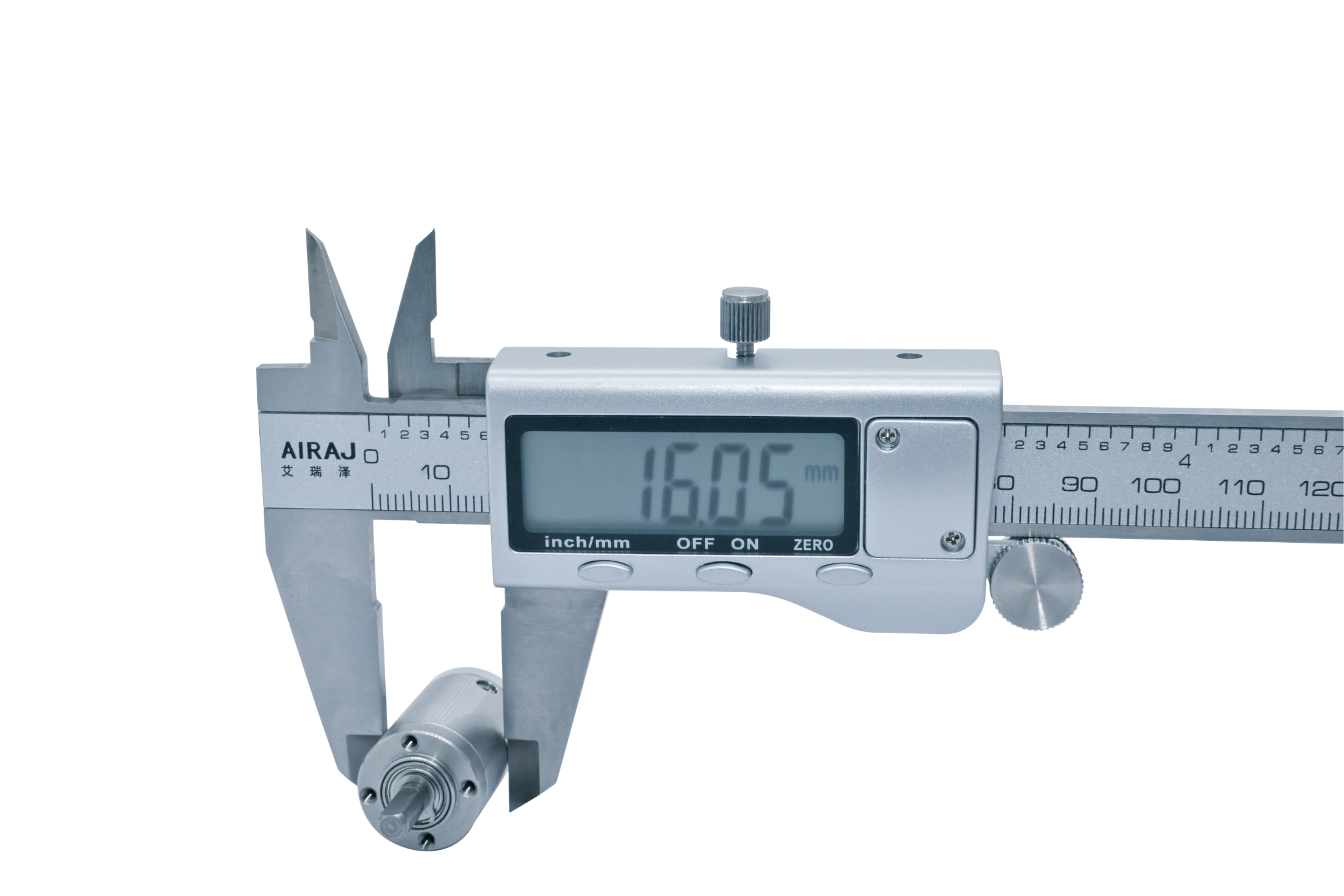
Product Identity
| Item | Description |
|---|---|
| Model | 16P |
| Product type | Micro precision planetary gearhead (planetary gearbox) |
| Nominal outer diameter | 16 mm |
| Number of stages | 1 to 4 |
| Housing material | Steel |
| Gearwheel material | Steel |
| Output bearing | Ball Bearing |
Key Specifications
| Parameter | Published value |
|---|---|
| Nominal outer diameter | 16 mm |
| Gearhead length range | 17.55–30.45 mm |
| Reduction ratio range | 3.85:1–459.5:1 |
| Rated allowable torque range | 392.3–882.6 mN·m |
| Maximum momentary torque range | 784.5–2549.7 mN·m |
| Efficiency range | 66–90% |
| Backlash at no load | ≤ 1.5° |
| Permissible gearhead input speed, continuous operation | Motor/configuration dependent; confirm selected operating point |
| Operating temperature | −40 to 120 °C |
Maximum momentary torque is not a continuous working rating.
Stage, Ratio and Performance Table
| Stages | Gearhead length L | Available reduction ratios | Rated allowable torque | Maximum momentary torque | Efficiency |
|---|---|---|---|---|---|
| 1 | 17.55 mm | 3.85 / 4.33 / 4.63 | 392.3 mN·m | 784.5 mN·m | 90% |
| 2 | 21.85 mm | 14.8 / 16.7 / 17.8 / 18.7 / 20 / 21.4 | 490.3 mN·m | 980.7 mN·m | 80% |
| 3 | 26.15 mm | 57.1 / 64.2 / 68.6 / 72.2 / 77.2 / 81.2 / 82.5 / 86.8 / 92.8 / 99.25 | 686.5 mN·m | 1961.3 mN·m | 73% |
| 4 | 30.45 mm | 219.7 / 247 / 264.2 / 277.9 / 297.2 / 312.55 / 317.75 / 334.2 / 351.5 / 357.4 / 375.9 / 382.1 / 401.9 / 429.8 / 459.5 | 882.6 mN·m | 2549.7 mN·m | 66% |
Shaft and Load Limits
| Parameter | Published value |
|---|---|
| Radial load, measured 10 mm from flange | ≤ 1.6 kgf |
| Shaft axial load | ≤ 0.5 kgf |
| Radial shaft play | ≤ 0.04 mm |
| Thrust shaft play | ≤ 0.2 mm |
Motor Compatibility
For motor + gearhead matching, use the downloadable gearhead Datasheet and the motor Datasheet library. Motor voltage/power, shaft/pinion, pilot, mounting, input speed and duty-cycle compatibility must be confirmed for the exact combination; older marketing charts are not a technical specification.
Dimensions and Interface
The published drawing shows a 16 mm body, an 11.6 mm output-shaft extension and stage-dependent gearhead lengths of 17.55, 21.85, 26.15 and 30.45 mm. Download the official 2D Drawing PDF above for the complete shaft, mounting, input-interface and tolerance notation.
STEP Notes
The Full Assembly STEP is the published original Creo assembly. The Simplified STEP is a separate 4-stage reference for preliminary mechanical packaging. The 16P 2D outline drawing is the original SG01PD16 interface reference. The body length L ±0.3 mm is configuration-dependent; confirm stage, ratio and motor mating dimensions before production.
Back to the 8–42 mm product catalogue
Potential OEM applications (suitability requires engineering review): Motorized curtains · HVAC vent dampers · Smart appliance lid motions · Smart hardware · All applications.
Motor + Gearhead Assembly: Motor matching and custom integration.