10 mm Micro Planetary Gearhead (10P)
Download Datasheet PDF Download 2D Drawing PDF Download Full Assembly STEP Download Simplified 4-Stage STEP · Reference
Engineering data reference: Use the current 10P Datasheet PDF for published input-speed conditions, ratio/stage, rated load and dimensions. Images here show real products only; if a web summary and the downloadable Datasheet differ, verify the latest controlled revision with SigGear engineering.
| Ø Diameter | Reduction ratios | Gearhead body length | Rated allowable torque | Backlash |
|---|---|---|---|---|
| 10 mm | 3.5:1–428.7:1 | 10.25–18.50 mm | 127.5–196.1 mN·m | ≤ 1.5° |
Custom 10P interface or motor fit? Match my motor · Review my drawing / STEP · Replace / redesign existing gearbox · Prototype → volume
More: Stage-by-stage ratios · Online technical specifications · Official 2D Drawing PDF · Motor-only datasheets · All 12 models
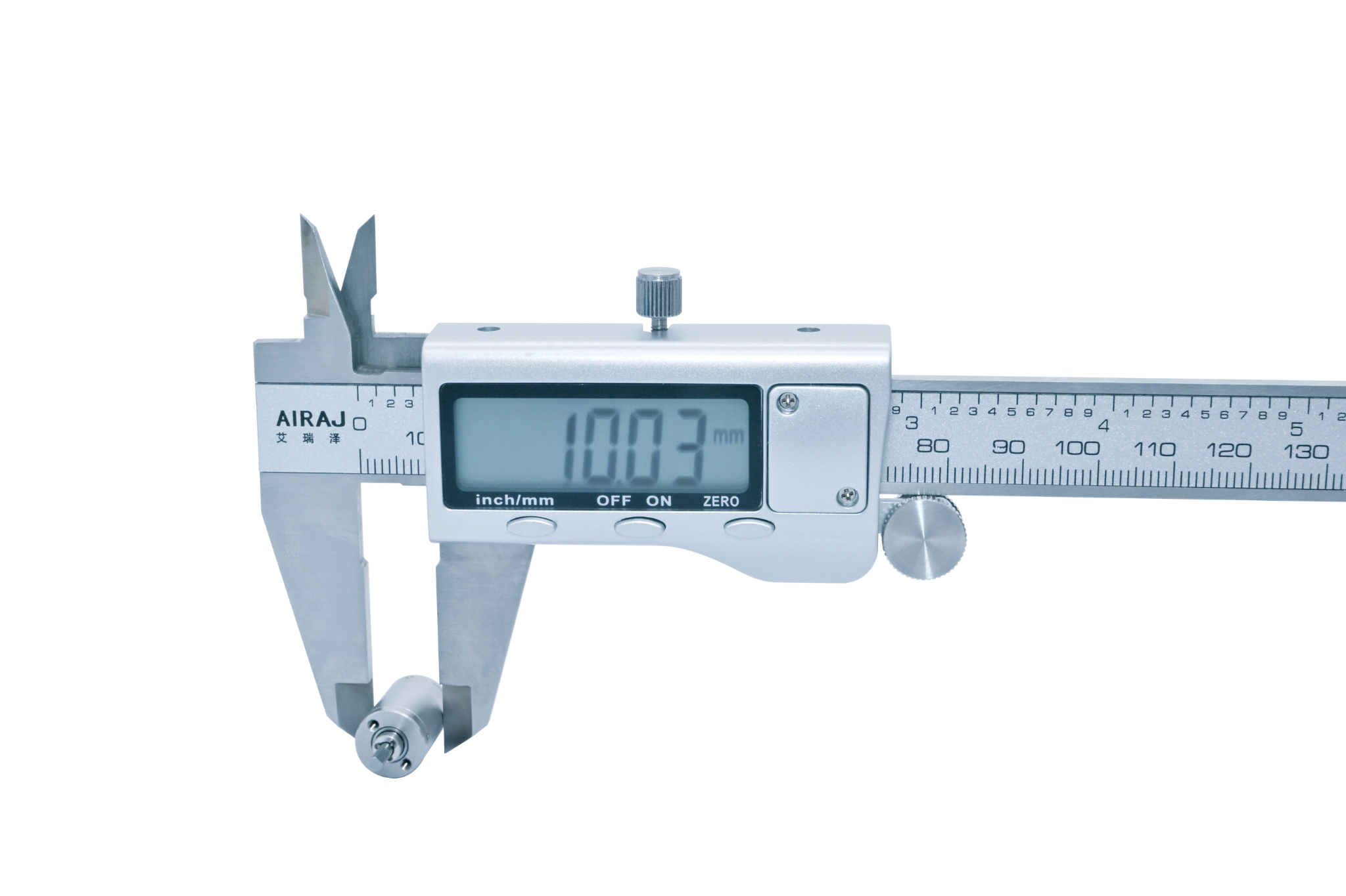
Construction: steel housing and gearwheels · ball bearings · 1–4 stages. Gearhead-only or motor-mated assembly after interface review.
Key Specifications
| Parameter | Published value |
|---|---|
| Nominal outer diameter | 10 mm |
| Gearhead length range | 10.25–18.50 mm |
| Reduction ratio range | 3.5:1–428.7:1 |
| Rated allowable torque range | 127.5–196.1 mN·m |
| Maximum momentary torque range | 255.0–392.3 mN·m |
| Efficiency range | 66–90% |
| Backlash at no load | ≤ 1.5° |
| Permissible input speed | Motor/configuration dependent; confirm selected operating point general reference; not a universal ceiling for every motor combination |
| Operating temperature | −40 to 120 °C |
Maximum momentary torque is not a continuous working rating.
Stage, Ratio and Performance Table
| Stages | Gearhead length L | Available reduction ratios | Rated allowable torque | Maximum momentary torque | Efficiency |
|---|---|---|---|---|---|
| 1 | 10.25 mm | 3.5 / 4 / 4.75 | 127.5 mN·m | 255.0 mN·m | 90% |
| 2 | 13.00 mm | 12.25 / 14 / 16 / 16.6 / 19 / 22.6 | 147.1 mN·m | 294.2 mN·m | 80% |
| 3 | 15.75 mm | 42.9 / 49 / 56 / 58.2 / 64 / 66.5 / 76 / 79 / 90.25 / 107.2 | 176.5 mN·m | 353.0 mN·m | 73% |
| 4 | 18.50 mm | 150.1 / 171.5 / 196 / 203.7 / 224 / 232.7 / 256 / 266 / 276.4 / 304 / 315.9 / 361 / 375.1 / 428.7 | 196.1 mN·m | 392.3 mN·m | 66% |
Shaft and Load Limits
| Parameter | Published value |
|---|---|
| Radial load, measured 10 mm from flange | ≤ 0.6 kgf |
| Shaft axial load | ≤ 0.15 kgf |
| Radial shaft play | ≤ 0.04 mm |
| Thrust shaft play | ≤ 0.15 mm |
Motor Compatibility
For motor + gearhead matching, use the downloadable gearhead Datasheet and the motor Datasheet library. Motor voltage/power, shaft/pinion, pilot, mounting, input speed and duty-cycle compatibility must be confirmed for the exact combination; older marketing charts are not a technical specification.
Dimensions and Interface
The published drawing shows a 10 mm body, a 7.50 mm output-shaft extension and stage-dependent gearhead lengths of 10.25, 13.00, 15.75 and 18.50 mm. Download the official 2D Drawing PDF above for the complete shaft, mounting, input-interface and tolerance notation.
STEP Notes
For the 10P, certain HS-1013-Q / HS-1015-Q windings can reach 26,000–31,000 rpm at no load; this is not a continuous-speed rating. Confirm the permissible operating point for the exact motor + gearhead combination.
The Full Assembly STEP is the original Creo assembly export for 10P, now available for direct download. The separate Simplified STEP is a 4-stage reference model for preliminary packaging. For dimensional verification, use the downloadable 2D Drawing PDF and confirm its controlled production revision.
Back to the 8–42 mm product catalogue
Potential OEM applications (suitability requires engineering review): Smart locks · Paper-feed mechanisms · Medical device auxiliary motion · Precision instruments · All applications.
Motor + Gearhead Assembly: Motor matching and custom integration.